In this blog I’m going to explain how I made a ‘pop-up’ TV with a functioning screen showing pixel animations. There is a ‘remote’ controlling the ‘channels’- so when a button is pressed a new animation is presented on the screen.
Pop Up Design
The design for my pop up went through several iterations. I wanted my TV to look like a 1960s CRT – so a relatively simple design of a solid box with a lid on top. I first used Duncan Birmingham’s pop up box design however instead of a pitched roof, my box has a flat top. Unfortunately this was the design’s undoing as the lid of the box kept on getting stuck and not folding away properly.
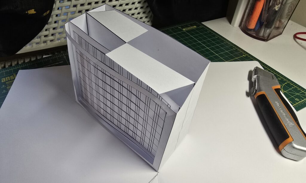
However I saw this box design by Matthew Reinhart and it worked perfectly! The lid even has a fold (or ‘gully’) where I can build a pair of antenna or ‘rabbit-ears’ as they were called. Under the lid itself I had a bit of ‘scaffolding’ to keep the lid up at a certain height. In Matthew’s video, he makes the scaffolding length equal to the height of the box, however I found that the lid seemed to dip too low when the pop up is fully opened. To correct this, I doubled up the thickness of the scaffolding to give it some more strength and made it slightly longer than the box height.
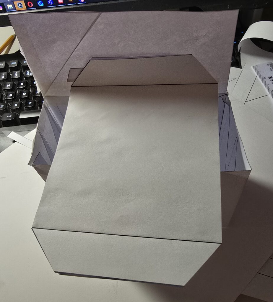
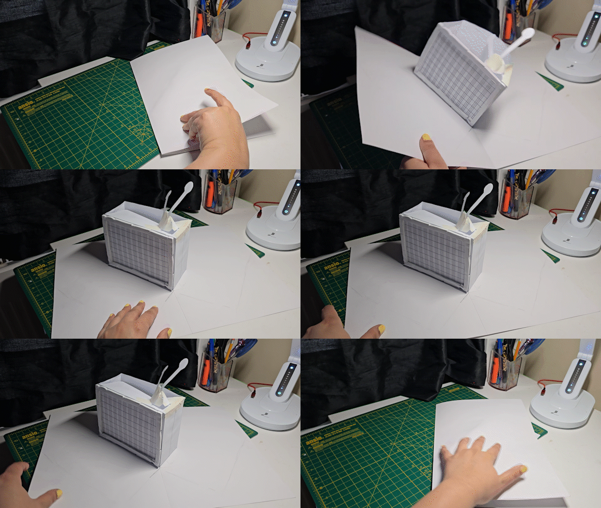

Here’s my PDF file for my pop up so you can create your own!
Creating the LED Matrix
I wanted to use this high density 144 pixels/m LED tape. I couldn’t simply cut the tape into the length of my rows because I wanted the individual LEDs to be in a perfect grid pattern (I.e. equidistant from each other) so that the animations I played would be undistorted. So I cut out all the LEDs, placed and soldered them together with what felt like a million tiny bits of tinned copper.
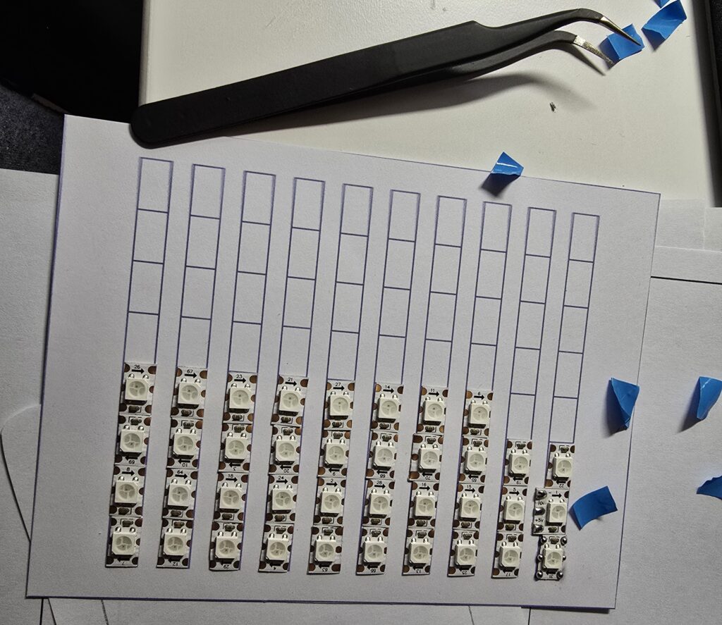
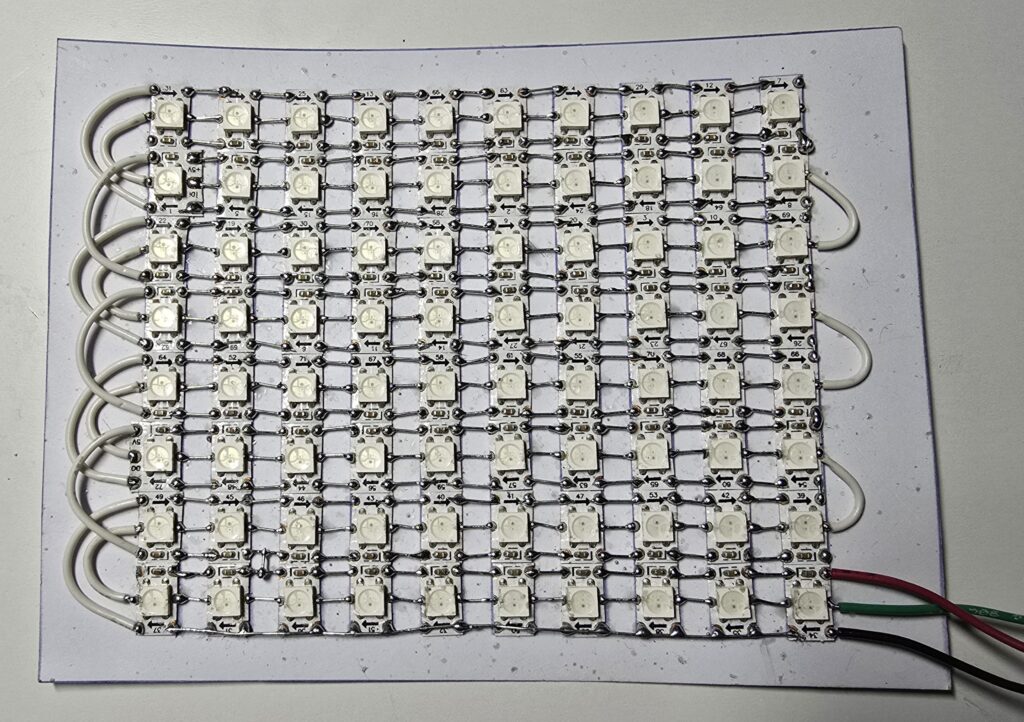
This was some of the most challenging soldering I’ve ever done, especially the data line, as the copper pad was tiny – also the copper pads just weren’t as easy to solder as other tapes I’ve used; I suspect there was a thicker ‘coating’ on the pads themselves. I scrubbed at the pads with an abrasive pencil to try and make the solder stick faster. Additional rosin flux would have made it easier but would have soaked into the paper.
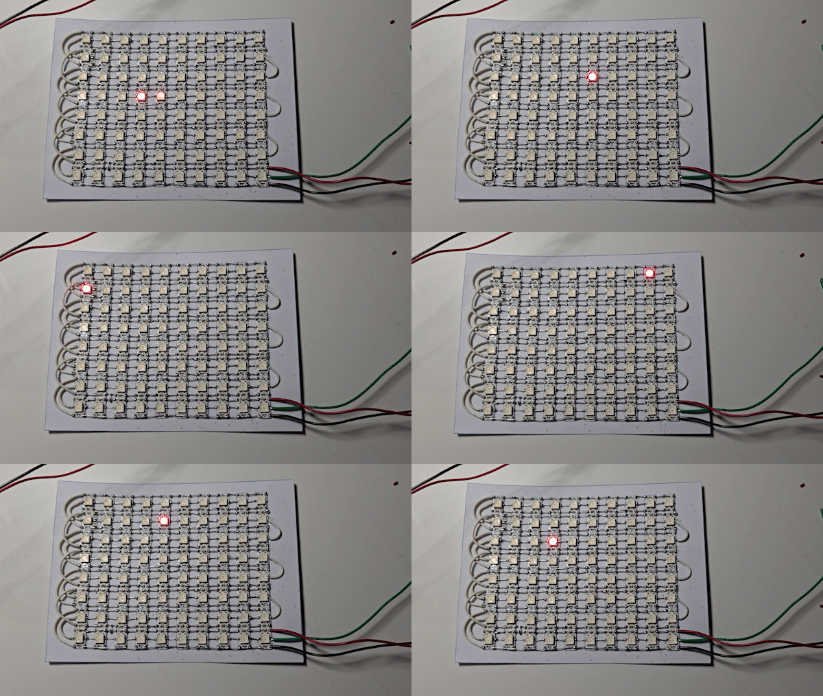
I quickly tested that my matrix worked with Scott Marley’s moveLED FastLED code.
Code
My aim was to somehow be able to play gifs on my LED Matrix and to choose between several animations by pressing buttons. There would be 4 animations paired with 4 different buttons.
I first tried out a great little tool by TylerTimoJ called LMCSHD which worked perfectly displaying an animation on my LED Matrix. The software was easy to use and unlike a lot of other similar software I checked out, could handle an LED Matrix of any pixel dimension – mine was 8×10. I tested it out with a pacman gif…
However, even though it played an animation , there was no way (that I could figure out) to load multiple animations and control them with buttons.
I then came across this intriguing article by Suramya Das.
His script seemed to promise exactly what I needed, to extract the colour data for each pixel of each frame of the gif and convert that into an array that I could apply to my LED Matrix using FastLED. Unfortunately it didn’t work. Python isn’t my expertise so I roped in my brother to help- he fixed a few code issues. Here is the repo for the corrected python script.
This animations ran fine HOWEVER… I encountered a BIG problem when I introduced buttons. The first button I pressed would play the selected animation just fine but when I pressed any other button, the animation would stay the same – it was like as if the button ‘presses’ weren’t being registered by the Arduino. I tested by button code using fill_solid() with different colours.
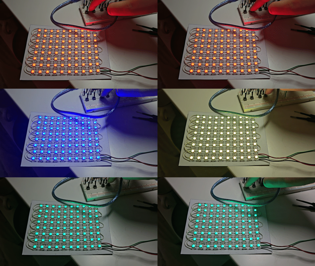
It worked perfectly so it was definitely an issue with the generated arrays not my button code. I figured out that the issues were arising because Suramya’s script used delay() in between the frames. But delay() is a blocking function, while it runs it prevents any other code from executing… but the ESP32 needs to ‘hear’ the button ticks while the frames of the animation are running.
So I changed up the code to use millis() and asked my brother to help out again with changing the Python script so it generates the pixel/frame data in a way that makes it convenient to copy paste into my code.
And it worked perfectly! I also think the array data turned out looking a lot neater than in the original script. Note that your LED Matrix needs to be connected in a zigzag style (not sequence) for it to work.

Also the generated animation is ‘upside down’. I simply saved my gifs ‘upside down’ in photoshop which were then turned around the ‘right way’ when its run through the script.
Here’s a link to the new Python Script.
And here’s a link to the ESP32 code.
I made the gifs for the 4 channels in photoshop. With only 80 (8×10) pixels to work with, I found it pretty difficult making animations – simple shapes and movements definitely translate better. When I first uploaded my animations, some of the colours looked dark – I realised this was because I was using desaturated colours in my design – so I replaced them with fully saturated colours- this made shading objects difficult, something I’ll have to practice.
In my next blog post, I’ll be finishing off my TV Pop Up! : )
