I got a basic grounding in FastLED with this excellent set of tutorials by Scott Marley and knew I wanted to use Fastled in a project so decided to make a choker!
Materials
Collar from Amazon. To use as the actual choker itself I bought this dog collar – bit weird I know but the leatherette material and buckle is a much sturdier material + fastening than using a choker made of fabric with ribbon clamps – especially as I plan to affix the circuitry to the back of the choker.. So the dog collar is a cheap and strong alternative; plus no one will realise it’s a dog collar once the LED tape is stuck on!
5V pixel LED tape from Amazon. I got it in black so that it could blend in better with the dark colour of the choker. The LED tape is fairly good quality, VERY high density.
I will be drawing power from a small 5V USB power bank.
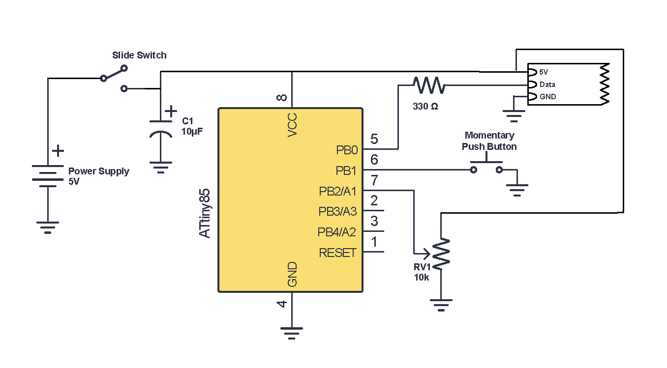
In terms of added circuitry, I wanted:
- A power button, to switch power from a 5v source.
- Push button to cycle between patterns.
- Potentiometer to control brightness values.
- Microcontroller to load patterns on to and control brightness with the pot – I used an ATTiny85. I also bought an IC socket so I can easily remove the microcontroller and reprogram.
- A 330Ω resistor on the data pin of the LED tape, the attiny85’s I/O pin has a limit of 30mA DC, in reality the data line on a LED tape draws a tiny amount of current (~µA) but better safe than sorry.
- A capacitor to smooth out the DC power.
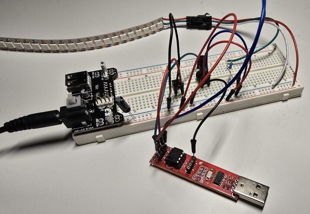
I assembled all of this on a breadboard according to the following schematic (I used Circuit Canvas + Illustrator to make this diagram):


Programming the Microcontroller
I bought the SparkFun Tiny AVR programmer to make programming the ATtiny85 super easy (although you can do it with an Arduino UNO/Nano it just requires a bit of breadboard space)
I followed the instructions on the link above to get it installed and then on the Arduino IDE, under the Tools menu I picked the following options:
Programmer > USBtinyISP
Processor > ATtiny85
Clock > Internal 8 Mhz (The external clock is for when you use an external crystal oscillator in conjunction with the ATtiny. I find the internal clock good enough for what I’m doing)
The Port option doesn’t matter.
At this point, I plugged the AVR programmer in and uploaded my code to the microcontroller…. but I couldn’t get it to work. After hours of pulling out my hair I figured out you need to ‘Burn Bootloader’ (also under the Tools menu) after you change the clock speed.
Code
My code is at the bottom of this page. Much of it is based on Scott’s work on his Github.
You can safely draw a maximum of 500mA from a standard USB power supply. I capped the maximum current draw by capping the maximum brightness that could be set for the tape in the code. When the pot is turned all the way up, FastLED.setBrightness is given a max value of 100 (out of 255). I measured the current draw at this (max) brightness when the tape was set on white, and measured a draw of 430mA. Considering that none of my final patterns will be full static white, any patterns I have will have a safe amount of current draw.
I tried a few of the more complicated premade patterns from Scott’s page e.g. Pacifca. When I tried them out, they seemed to run slowly, and there was some ‘jittering’ across the tape. I’m not sure if it’s a software or hardware issue, I’m going to investigate later.
I also initially used his crossfading code, when you press the button to change the patterns, the patterns will fade into each other in a very pleasing way instead of just abruptly changing. This worked perfectly using the Arduino UNO but the ATtiny simply doesn’t have enough memory.
The Result
And here’s the led tape working! In the video, I’m using the button to change patterns and the potentiometer to change the brightness.
Stuff for next time:
- Build the circuit on to a piece of perf board. Attach the tape and circuitry to the choker.
- Put ferrules on the end of the USB cable. I read that putting stranded wire into a screw terminal isn’t the best because the stranded wire eventually ‘squeezes’ out – so I’m going to put some ferrules on the end of the wire to give them some solidity.
- Personalise Scott’s FastLED patterns. I copypasted from his Github, but I’m going to change them up a bit. https://github.com/s-marley/FastLED-basics/tree/main/1.%20Getting%20started)
- Buy a slide/rocker switch to switch power instead of a latching push button. I want there to be a tactile difference between the power switch and the pattern switch, so that the wearer of the choker doesn’t press the wrong button when reaching around behind their neck.
- Some design decisions: I’m considering covering the choker in velvet and poking some eyelets into it so you can see the LEDs. And maybe having a layer of diffusion in between the velvet and the LEDs. I’m not sure how well it will work being so close to the LEDs so maybe there’s a way of raising the diffusion slightly off the LEDs so there’s a more noticeable diffusion effect. Much experimentation required!
#include <FastLED.h>
#include <OneButton.h>

#define NUM_LEDS 38
#define LED_PIN 0
#define BTN_PIN 1
#define POT_PIN A1

CRGB leds[NUM_LEDS];
uint8_t brightness = 50;

uint8_t patternCounter = 0;

// Push button connected between pin 7 and GND (no resistor required)
OneButton btn = OneButton(BTN_PIN, true, true);

void setup() {
  FastLED.addLeds<WS2812B, LED_PIN, GRB>(leds, NUM_LEDS);
  FastLED.setBrightness(50);
  pinMode(POT_PIN, INPUT);

  btn.attachClick(nextPattern);
}

void loop() {

  int potValue = analogRead(POT_PIN);
  brightness = map(potValue, 0, 1023, 0, 100);
  FastLED.setBrightness(brightness);

  switch (patternCounter) {
    case 0:
      movingDots();
      break;
    case 1:
      rainbowBeat();
      break;
    case 2:
      redWhiteBlue();
      break;
    case 3:
      solidWhite();
      break;
  }

  FastLED.show();
  btn.tick();
}

void nextPattern() {
  patternCounter = (patternCounter + 1) % 4;  // Change the number after the % to the number of patterns you have
}

//------- Put your patterns below -------//

void movingDots() {

  uint16_t posBeat = beatsin16(30, 0, NUM_LEDS - 1, 0, 0);
  uint16_t posBeat2 = beatsin16(60, 0, NUM_LEDS - 1, 0, 0);

  uint16_t posBeat3 = beatsin16(30, 0, NUM_LEDS - 1, 0, 32767);
  uint16_t posBeat4 = beatsin16(60, 0, NUM_LEDS - 1, 0, 32767);

  // Wave for LED color
  uint8_t colBeat = beatsin8(45, 0, 255, 0, 0);

  leds[(posBeat + posBeat2) / 2] = CHSV(colBeat, 255, 255);
  leds[(posBeat3 + posBeat4) / 2] = CHSV(colBeat, 255, 255);

  fadeToBlackBy(leds, NUM_LEDS, 10);
}

void rainbowBeat() {

  uint16_t beatA = beatsin16(30, 0, 255);
  uint16_t beatB = beatsin16(20, 0, 255);
  fill_rainbow(leds, NUM_LEDS, (beatA + beatB) / 2, 8);
}

void redWhiteBlue() {

  uint16_t sinBeat = beatsin16(30, 0, NUM_LEDS - 1, 0, 0);
  uint16_t sinBeat2 = beatsin16(30, 0, NUM_LEDS - 1, 0, 21845);
  uint16_t sinBeat3 = beatsin16(30, 0, NUM_LEDS - 1, 0, 43690);

  leds[sinBeat] = CRGB::Blue;
  leds[sinBeat2] = CRGB::Red;
  leds[sinBeat3] = CRGB::White;

  fadeToBlackBy(leds, NUM_LEDS, 10);
}

void solidWhite() {
  fill_solid(leds, NUM_LEDS, CRGB::White);
}
